 .
.
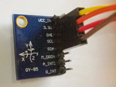
Exemple de réalisation d'un inclinomètre avec le module GY85.
Composants utilisés
- 1 carte Arduino UNO
- 1 Centrale inertielle 9 axes (Accéléromètre + gyroscope + boussole) GY-85
(ITG3205 +ADXL345 + HMC5883+ BMP085) - Fils de branchement Dupont mâle / femelle
Principe de fonctionnement
Fonctions embarquées :
Ce module regroupe en un seul circuit toutes les fonctions nécessaires à la réalisation d'une centrale inertielle complète.
Il comporte 9 axes (9 DOF) au total, avec 3 axes d'accéléromètre (Ax, Ay, Az), 3 axes de gyroscope (Rx, Ry, Rz), et 3 axes de champ magnétique, boussole (Bx, By, Bz).
Les capteurs
Capteur BMP085 de pression atmosphérique (Bosch), pour la détermination de l'altitude ou de la profondeur (300 à 1100 hPa), avec convertisseur rapide (7.5 ms max) et faible bruit en mode haute résolution (0.03 hPa ou 0.25 m), ou en mode basse consommation (0.06 hPa et 0.5 m).
Capteur ITG3205, gyroscope trois axes digital (InvenSense), avec triple convertisseur analogique/numérique 16 bits, et interface I2C rapide (400 kHz), communication en 2 fils. Il comporte un filtre passe bas digital programmable, faible courant consommé (6.5 mA). Il mesure la vitesse de rotation angulaire.
Capteur ADXL345, accéléromètre (Analog Device) trois axes à forte résolution 13 bits, jusqu'à +- 16g, sortie formatée en 16 bits sur le bus I2C. Il mesure la pesanteur, les chocs, les mouvements d'accélération. Il permet de détecter des changements d'inclinaisons de moins de 1 degrés. Possibilité de détection de mouvement ou d'arrêt (acticity sensing), de chute du capteur (free fall sensing), et tap sensing.
Capteur HMC5883L de champ magnétique sur 3 axes (Honeywell), capable de détecter de faibles champs, pleine échelle +- 8 Gauss, résolution de 5 milli-Gauss. Communication simple par bus SPI.
 .
.
Caractéristiques
- Alimentation du PCB 3.3 - 5V.
- Entièrement compatible avec les dispositifs 3.3 à 5 V, avec circuit IIC inclus.
- Idéal pour votre carte Arduino, RPi...
- Taille 22 x 17 mm
- Un trou de fixation est disponible (3.07 mm de diamètre)
Câblage
Module --> Carte Arduino
- Vcc_in non utilisé
- 3.3V --> 3.3 V alimentation Arduino
- GND --> GND Arduino
- SCL -->A5 arduino
- SDA --> A4 arduino
- M_DRDY non utilisé
- A_INT1 non utilisé
- G_INT non utilisé
 .
.
Exemple de code : un inclinomètre
Installer la librairie FreeSixIMU disponible ici
https://github.com/spaceappsatlanta/ard ... dLibraries
Puis charger ce code d'exemple.
Il affiche les 3 angles du module et son degré d'inclinaison.
La communication se fait en I2C.
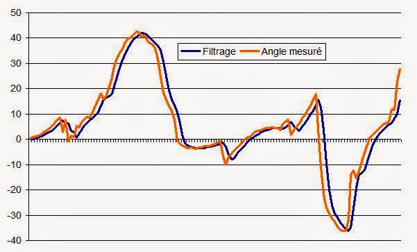
Un filtre de Kalman permet de fusionner les données du gyroscope et de l'accéléromètre. On filtre ici les mesures brutes par une moyenne glissante pour les lisser.
- Code: Tout sélectionner
//************************************************************
// demo_imu_6dof tiptopboards 27 10 2014
// modifé selon :
//************************************************************

//John Dingley 08/03/2014   IMU TESTING PROFRAM
//This program modified slightly from Piddybot program see below. If you wire up the Sparkfun Digital IMU and connect
//the USB lead to your computer and open the Serial View window (9600 Baud)
//then when you move the IMU from the flat position you will see the displayed "angle" varies from zero when level
//through -ve values when tilted one way to +ve similar sized values when tilted the other way.

//This code therefore allows you to test your IMU is working OK and talking to the Arduino before attaching the Sabertooth power controller
//or attaching the deadman switch, steering rocker switch or the balance point fine tuning rocker switch.

// Modified from PIDDYBOT Self Balancing Program
// Program Written and Pieced together by Sean Hodgins.
// The program was morphed from many programs.
// With that being said If you feel you see something that
// is your work and want credit, feel free to contact me.
// Http://Idlehandsproject.com
// This is free to be shared, altered, and used.
// It is in no way "Finished".
// Find the Second target angle and tune for your bot, it may be different.
// LIBRARIES
#include <Wire.h>
#include <FreeSixIMU.h>
#include <FIMU_ADXL345.h>
#include <FIMU_ITG3200.h>

FreeSixIMU sixDOF = FreeSixIMU();


 const int AvgAngles = 3;
 float prevTargetAngle = 0;
 float targetAngle = 0;


float angles[5];

float currAngle, prevAngle;
float prevAngles[AvgAngles];
int prevAngleI = 0;

// time vars
int currTime = 0;
int prevTime = 0;


float errorSum = 0;
float currError = 0;
float prevError = 0;
float iTerm = 0;
float dTerm = 0;
float pTerm = 0;

//Location PID CONTROL - These are the PID control for the robot trying to hold its location.
  float Lp = 0.5;
  float Li = 0.05;
  float Ld = 0.4;
  float offsetLoc = 0;
  float pT,iT,dT = 0;
  float errorS = 0;
  float prevE = 0;

void setup() {


  // Serial Connection
  Serial.begin(9600);

  // IMU Connection
  Wire.begin();

  delay(5);
  sixDOF.init(); //Begin the IMU
  delay(5);

}


void loop() {

  updateAngle();
  Serial.print("lisse ");
  Serial.print(currAngle);  //Valeur lissée par moyenne
  Serial.print("  ");
  delay(200);

}


void updateAngle() {
  sixDOF.getYawPitchRoll(angles);
  // affichage de verification
  Serial.print(" brut ");
  for(int i=0; i<=2; i++)
   { Serial.print(angles[i]);
    Serial.print(' ');
  }
     Serial.println(' ');
  //
  prevAngles[prevAngleI] = angles[1];
  prevAngleI = (prevAngleI + 1) % AvgAngles;
  float sum = 0;
  for (int i = 0; i < AvgAngles; i++)
      sum += prevAngles[i];
  currAngle = sum / AvgAngles;
  prevAngle = currAngle;

}
L'angle d'inclinaison du module, mesure brute et filtrage.
Références
Arduino + Processing + capteur GY85 (vidéo en anglais) https://www.youtube.com/watch?v=Wu_fSQcAxRs
Exemple d'application : équilibrer un Segway (self balacing)
http://www.instructables.com/id/Arduino ... g-the-IMU/
Charger les librairies FreeSixIMU dans mes Documents/Arduino/librairies depuis
https://github.com/spaceappsatlanta/ard ... dLibraries
Code de test de l'IMU
http://www.instructables.com/files/orig ... HDU23L.txt

